
Proper Earth Grounding in Mississippi Poultry Houses Can Prevent Lightning Damage
Lightning strikes are a significant concern for poultry growers in the Southeast United States. Strikes can cause fires and destroy housing equipment such as controllers and motors. Some locations tend to be more prone to lightning strikes, and growers in those areas have suffered multiple strikes and significant equipment losses, while many growers have never been affected. Proper earth grounding of house structures, electrical systems, and equipment is necessary for a safe and efficient electrical system that can minimize the damage caused by lightning strikes.
Proper electrical grounding is more important today than in years past. Equipment advances such as electronic controllers and tunnel ventilation systems have provided growers increased control of the house environment and bird performance, but they have also increased vulnerability to catastrophic bird losses from lightning-induced electrical failures or ordinary power outages. To minimize losses from power outages, backup generators are a necessity on today’s modern poultry farms. In addition, some poultry house insurers are encouraging stronger fire protection strategies, including more robust electrical grounding systems to protect houses from the damage caused by lightning.
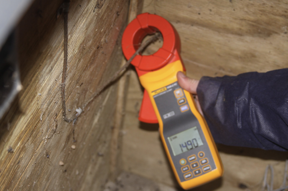
Electrical grounding systems create a pathway for the large amounts of electrical current created by lightning to reach earth ground. This pathway is important because, in electrical systems that are not grounded or improperly grounded, the electrical current from a lightning strike is forced through to generators, generator transfer switches, controllers, feed bin motors, etc., to find earth ground. Any equipment in an ungrounded or improperly grounded system that experiences excess current from a strike will be damaged and can catch fire. You can prevent equipment damage and fires by reducing the resistance in the path for lightning-induced current reaching to earth ground. Electrical resistance can be measured with a ground resistance meter like the one shown in Figure 1 and is reported in ohms (Ω). Prices for ground resistance meters vary from $250 to $2,000 and depend on the type and the manufacturer. According to the National Electrical Code (NEC), a properly grounded system should have an earth ground resistance of 25 Ω or less.
Telecommunications and more sophisticated electronic equipment have necessitated better grounding systems in poultry houses. A recent MSU survey of Mississippi broiler, broiler breeder, and pullet farms indicated that attention to electrical grounding systems has significantly improved over the last 20 years. The survey also indicated that grounding systems vary from farm to farm, mostly as a result of house age, electrical system modifications/updates, and electrician preference and attention to detail.
Components of a Typical Electrical Grounding System
Ground Rods
Ground rods are the most visible component of any grounding system. They are either copper-clad or galvanized steel rods that are usually 8–10 feet long and 5/8–3/4 inch in diameter. Longer ground rods have a better chance of contacting moist soil, which is important because moist soil carries current much better than dry soil. Grounding points in current poultry house construction commonly include feed bins, breaker boxes, generator transfer switches, generator frames, and wall footers. Grounding wall footers is also called a Ufer ground and is achieved by connecting the steel reinforcing rebar in the concrete to a ground rod (Figure 2). It is an acceptable method to reduce electrical resistance and increase grounding integrity. Ground rods should be located as close as possible to generator sheds, control rooms, and feed bins where they cannot be disturbed by lawnmowers, weed eaters, foot traffic, or any other equipment. Placing the ground rod inside the control room can help protect it from corrosion and other disturbances.
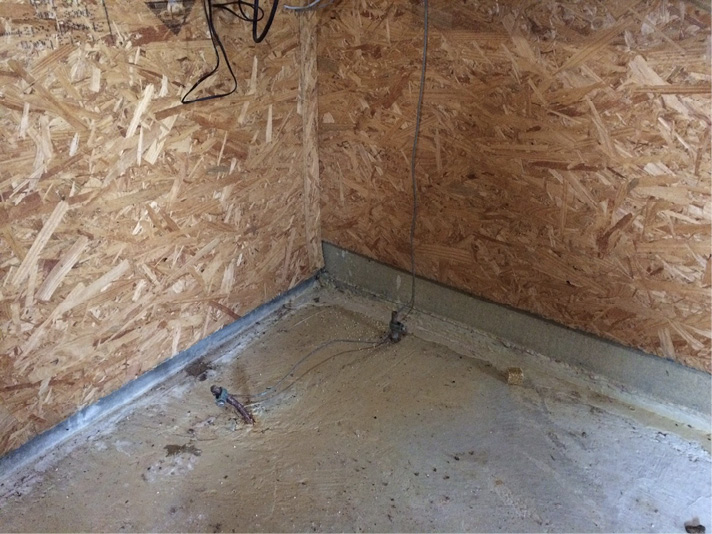
It is important to note that there should never be two independent ground rods close to each other. For example, there should not be a ground rod for the wall footer and a separate one for the control room breaker box. In this scenario, current dissipated from a lightning strike by the wall footer ground rod can travel through the soil, enter the adjacent rod and damage the controller. They should be bonded to a single ground rod as in Figure 2. It is also important that ground rods be driven into the ground to ensure good contact with the surrounding soil. Placing a ground rod in a hole that has been dug and then backfilling is not advised.
In a three-wire grounding system, each house is fed two load (hot) wires and a neutral. The equipment grounding wires and neutral wires are bonded together at each house breaker box and at the generator. This is a common and acceptable method of grounding, but a four-wire grounding system separates the neutral and ground wires at each house and provides extra protection for sensitive electronic equipment like alarms and controllers. Houses that have controllers or alarms that are networked together are susceptible to lightning damage and require surge protection. Current can be transmitted from house to house via telecommunication lines and can damage controllers and alarms (Stopping Lightning and Other Electrical Problems that Can Kill Birds. The Poultry Engineering, Economics, & Management Newsletter, No. 32. National Poultry Technology Center, Auburn University).
Ground Wire and Clamps
Six-gauge solid copper wire is commonly used to connect breaker boxes and equipment to a ground rod. Ground wire should be installed in such a way that it is not a tripping hazard, and longer wire runs should be buried underground. Ground wires that are not neatly installed tend to be the ones that get broken or disconnected. It is important to remember that a ground rod that is not connected to anything is useless in preventing damage or fire from a lightning strike.
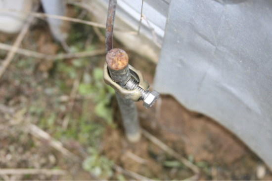
Acorn-type solid ground clamps are most commonly used to connect ground wire to ground rods. The acorn-style clamps have proven effective and durable and are generally preferred over two-piece clamps. A solid connection must be made between the ground wire and ground rod to ensure the integrity of a grounding system. Be sure to check grounding connections every year because they can loosen over time and, as mentioned earlier, ground wires do occasionally get broken (Figure 3).
Survey of Poultry Farm Grounding Systems
MSU tested earth ground resistance in multiple broiler, broiler breeder, and pullet houses in Mississippi (see Table 1). Where available, resistance data was collected at control room breaker boxes, feed bins, generator sheds, generator frames, and wall footers. The most consistent grounding locations were the control room breaker boxes, generator service entrances, and generator frames. Three of the nine farms tested had grounded feed bins, and all 22 of them were above the NEC recommended 25 Ω. Twelve of the 29 houses had resistances at the control room breaker box that were higher than the 25 Ω recommended by NEC. Only one farm had a Ufer or wall footer ground.
Table 1. Resistance results at commonly grounded locations for nine poultry farms (29 houses total) in Mississippi. Twelve of the 29 control rooms and all 22 of the feed bins tested were above the 25 Ω recommended by NEC.
|
Farm # |
Control Room Range (Ω) |
Control Room Average (Ω) |
Feed Bin Range (Ω) |
Feed Bin Average (Ω) |
Generator Service Panel1 (Ω) |
Generator Frame1 (Ω) |
Ufer Range (Ω) |
Ufer Average (Ω) |
Year Built |
Electrical Upgrade |
|---|---|---|---|---|---|---|---|---|---|---|
|
1 |
1–91 |
46 |
89–609 |
342 |
1 |
no data |
no ground |
no ground |
2018 |
no |
|
2 |
10–17 |
12 |
104–278 |
151 |
1 |
0.1 |
15–32 |
23 |
2016 |
no |
|
3 |
1–38 |
13 |
94–327 |
219 |
0.0 |
0.2 |
no ground |
no ground |
2015 |
no |
|
4 |
26–39 |
31 |
no ground |
no ground |
0.2 |
191 |
no ground |
no ground |
2011 |
no |
|
5 |
49–92 |
70 |
no ground |
no ground |
0.1 |
0.4 |
no ground |
no ground |
2009 |
no |
|
6 |
18–29 |
23 |
no ground |
no ground |
0.1 |
0.1 |
no ground |
no ground |
2007 |
no |
|
7 |
4–5 |
4 |
no ground |
no ground |
31 & 45 |
0.1 & 0.5 |
no ground |
no ground |
2001 |
yes (2013) |
|
8 |
0.1–41 |
16 |
no ground |
no ground |
0.2 & 19 |
0.2 & 0.3 |
no ground |
no ground |
1997 |
yes (2017) |
|
9 |
9–12 |
10 |
no ground |
no ground |
90 |
0.1 |
no ground |
no ground |
1996 |
yes (2017) |
1On Farms 7 and 8, two generator service panels and two generator frames were tested.
Take-Home Points
- Proper grounding is critically important in modern poultry houses to protect sensitive electronic equipment, mitigate damage from lightning strikes, protect birds, and prevent catastrophic losses.
- Ground rods placed inside control rooms and generator sheds are better protected from corrosion and from equipment that can damage rods and loosen connections.
- Loose or broken ground wires and clamps were found during MSU’s testing. It is a good idea to inspect all ground rods and clamps yearly.
- Acorn-type solid ground clamps are recommended over two-piece clamps.
- Resistances can be lowered by connecting two ground rods together. If resistances at a grounding location are deemed too high, adding another ground rod can reduce overall resistance.
- All feed bins tested had resistances higher than 25 Ω. Rust and corrosion were noticed in many of the feed bin grounds; cleaning the connection points, clamps, and ground wire may help reduce resistances. Installing additional grounding rods or a Ufer ground connected to the rebar in the concrete pad supporting the bins would also help.
- Resistance varies from house to house even on the same farm, so, if you are testing resistances, it is a good idea to check all of your houses.
- In new construction, Ufer grounds are a good idea. They are easy to install and are an additional layer of protection against lightning damage.
The information given here is for educational purposes only. References to commercial products, trade names, or suppliers are made with the understanding that no endorsement is implied and that no discrimination against other products or suppliers is intended.
Publication 3321 (POD-06-23)
Reviewed by Jessica Drewry, PhD, Assistant Professor, Agricultural and Biological Engineering. Written by John Linhoss, PhD, former Assistant Extension Professor, Agricultural and Biological Engineering; and Jody Purswell, PhD, USDA ARS Poultry Research Unit.

The Mississippi State University Extension Service is working to ensure all web content is accessible to all users. If you need assistance accessing any of our content, please email the webteam or call 662-325-2262.